Analysis & Documentation
Technical documentation
Comprehensive entry and outgoing analysis of ultrasound probes – Certified according to ISO 13485
Failure analysis on ultrasound probes / transducer
The probe analysis at ORTNER includes a wide range of test and analysis procedures. In this way, hidden defects on the transducer can be discovered on time before they lead to a loss of quality or a total failure.
A comprehensive analysis and complete documentation is the basis for our ISO 13485-certified repair of your ultrasound probe.

Standard Probe Performance Measurement – SPPM

Multipurpose Ultrasound Phantom
For quality control and maintenance of ultrasonic probes
- Measurement Depth of Penetration
- Capture non-echogenic targets
- Determination of different grayscale targets
- Suiteable for all linear, phased array, convex and TEE probes

Live test directly on the ultrasound device
We have a large number of ultrasound devices from all manufacturers
- Investigation for crystal failures
- Check for cable breaks
- Testing of color Doppler, tissue Doppler, CW-, PW-, M-mode

Leakage Test
Verification of electrical safety
- Direct measurement of the patient leakage current
- Pass/Fail diagnosis
- Can be performed for all transducers regardless of manufacturer

C-10 Probetester
Residual current measurement for TEE transducers
- Direct measurement of the patient leakage current
- Automated disinfection process for TEE probes
- Test report and documentation of the process after each run
Advanced Probe Performance Measurement – APPM
Capacitance Measurement
Status analysis of the sensors
An ultrasound probe consists of many individual elements, coaxial cables and power electronics. During the capacitance measurement, the total static capacitance is measured, which provides information about the aging and condition of the probe.
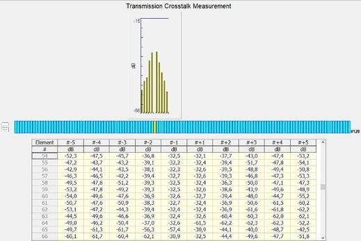
Transmission Crosstalk Measurement
The transmission crosstalk with Optimal Drive Waveform signal is defined and measured
This measuring method can be used to identify possible damage to the mechanical structure of the piezocrystals. For example, oxidation damage in the probe can be detected at an early stage.
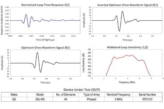
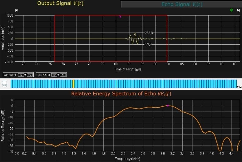
Intrinsic Characteristics Measurement
Comprehensive analysis of the internal sensors and components
- X (f) Normalized Loop Frequency Response
- X (t) Normalized Loop Time Response
- S-Loop (f) Wideband Loop Sensitivity
- B (t) Optimum Drive Waveform Signal
- S-LC Characteristic Loop Sensitivity


